Ford Focus IMRC problem is very common, and I suspect 80% of SVT owners need not replace the IMRC but simply clean the internal contacts.
So, do you have this problem? If you answer “no” to the following, it is 90% likely this procedure will work for you:
1) Is my cable broken?
2) Is my lever broken?
What you need:
1/4in ratchet with 8mm & 10mm sockets
Phillips screw driver #1 & #2
Soldering Iron
Thermal paste
RTV
Procedures:
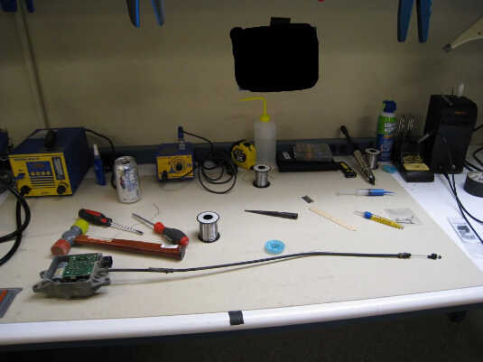
First, remove the drivers side headlamp, battery, battery tray, and airbox/uper half of CAI/SRI:
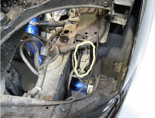
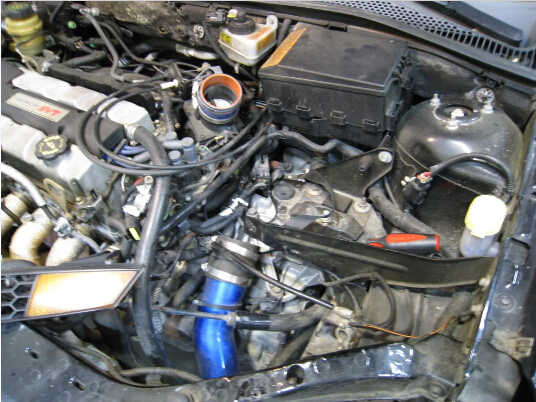
You see that the IMRC is located behind the headlamp.
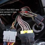
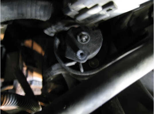
Now, before unbolting the IMRC box, disconnect the cable from the lever. This is done by (with one hand) roatating the lever towards you, while grasping the end of the cable and sliding it off of the post.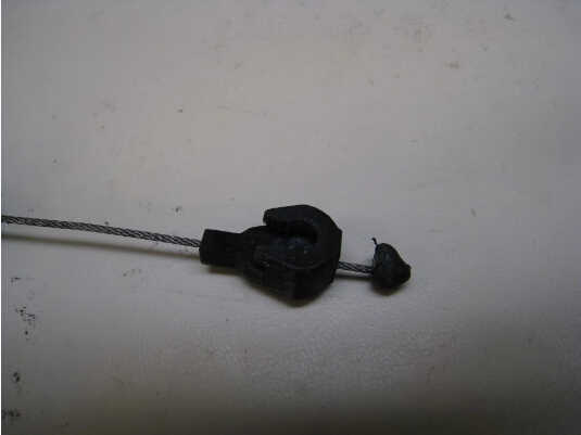
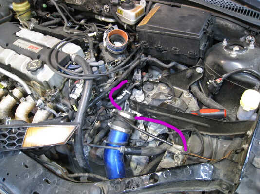
Now, unbolt the box and remove it while snaking the cable out along the path shown.
Ok, the hard part is done
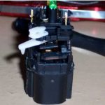
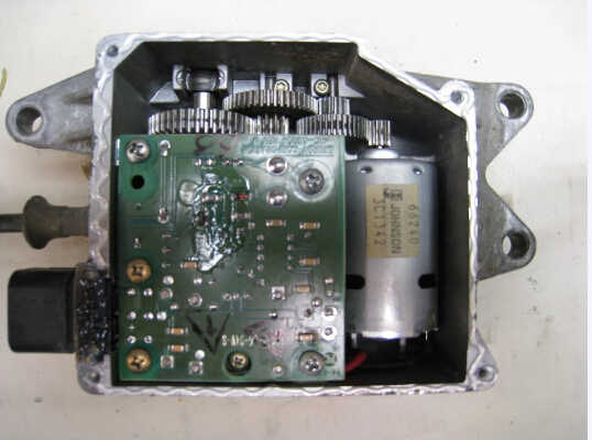
Next, take the IMRC to your bench to begin disassembly.
First, remove screws securing cover. Then using a straight razor blade cut around the seam to free the RTV.
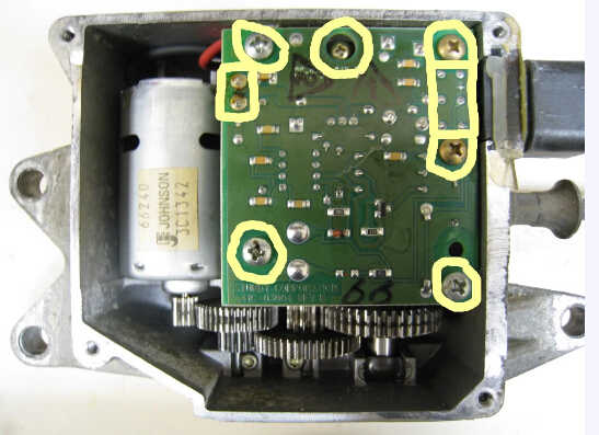
Now that the unit is open, remove the screws as shown, and desolder the power wires and connector pins.
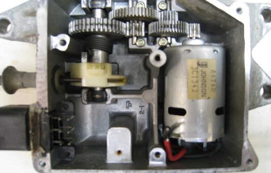
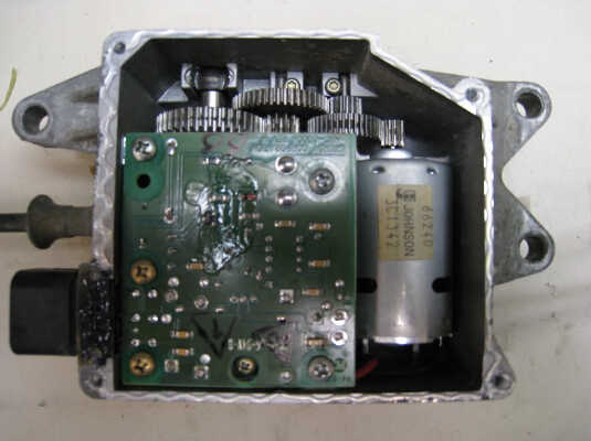
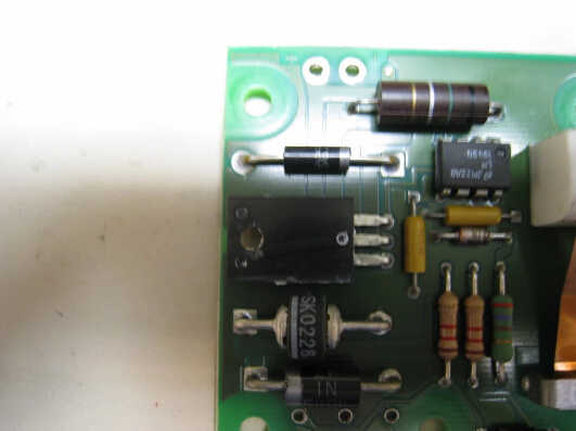
Remove PCB, and this is what you have.
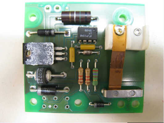
At this point you will notice, there is not much to this box. Notice the gears are made of metal, thus the odds they will ever strip is very slim. The electrical circuitis very simple as well, and failure of these components under normal operation is slim to none. The motor is nothing more than a glorified coil, and under normal operation coils are basically indestructable.
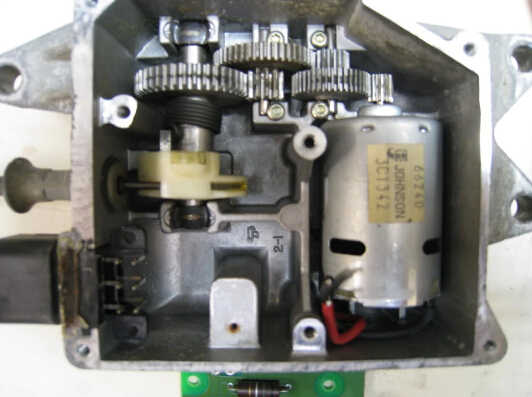
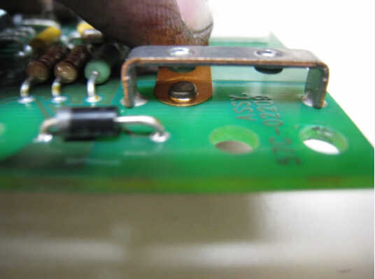
Leaving us with the true weak point of this unit… the contact Which is the copper strip with a nickel plated contact shown in the above picture.
Now, to remedy the dreaded P1518, we must burnish (clean) said contact.
Notice the grey color. This is not very condusive to conduction.
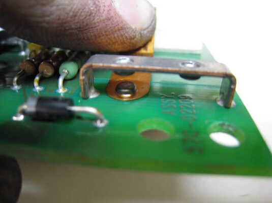
Using a piece of fine grit sand paper (paper), or a fine nail file (file), press down gently on the copper strip (DO NOT BEND COPPER STRIP),
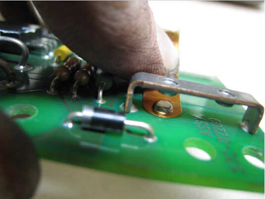
Insert paper/file, release copper strip and pull paper/file out. DO NOT MOVE BACK AND FORTH, SIMPLY PULL.
Repeat 3-5 times, and marvel at your new looking contact.
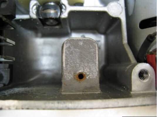
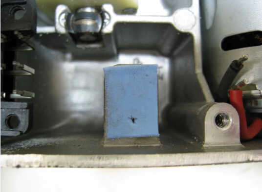
Now, before you reasemble the box, make sure your FET has enough remaining thermal grease to dissapate heat properly… In my case, I wiped it away and used thermally conductive gap pad.
Add thermal grease if you need to.
Now reattach the PCB the reverse of removal.
Using standard RTV, run a bead around the edge and screw the cover back on.
Bolt up the box to its bracket and run the cable along the same path you took it out of. BE SURE TO RUN THE CABLE INTO THE GROOVE BEHIND THE BATTERYTRAY, SO THAT WHEN YOU PUT THE TRAY BACK IN YOU DO NOT SMASH THE CABLE.
Hook up the cable end to the lever post by rotating the lever towards you and sliding the groove of the cable end on to the post.
Replace airbox/upper half CAI/SRI, battery tray, and battery.
Hook up battery… Start car… and enjoy your engine codeless dash