In order to pass state inspections, I recently had to replace the lower ball joints on my 2004 XLT Super Cab at 190K miles. All the other suspension and steering components on the front end are original and still serviceable. My hub bearing assemblies were also still good.
I sprayed all the parts to be disassembled with penetrating oil a couple of days before starting the work.
While I had things apart, I also took the opportunity to flush, clean, and lube the front brakes. I reassembled all suspension and steering component fasteners with antiseize and the halfshaft to differential flange bolts with Medium (blue) Loctite.
Here are some step by step guidelines and just a few photos.
Tools:
½ Drive Torque Wrench up to 150 ft.-lbs.
Ball Joint Press (OEM 27023)
Ford Ball Joint Adapter Set (27163)
Breaker Bar (& leverage pipe)
9 mm combination wrench or socket
10 mm combination wrench or socket
12 mm 12 point socket
13 mm socket
13 mm socket
18 mm socket
22 mm socket (Moog Lower BJ uses 22mm nut)
21 mm deep socket
24 mm deep socket
Various Socket Extensions
Pry Bar
External Snap Ring Pliers
3 lb sledge hammer
Good Quality All-Purpose Grease
Antiseize
Brake Cleaner
Penetrating Oil
Torque Values:
Halfshaft to differential to Differential Flange Bolts: 60 ft.-lbs.
Tie Rod: 85 ft.-lbs.
Upper Ball Joint: 85 ft.-lbs.
Lower Ball Joint: 95 – 111 ft.-lbs.
Axle Nut: 20 ft.-lbs.
Brake Bracket Bolts: 146 ft-lbs.
Caliper Pin Bolts: 22 ft.-lbs.
Removal:
1)Engage the emergency brake and chock the rear wheels. Jack up the front side with the wheel barely touching the ground and break the lug nuts loose. If you don’t have access to a lift, raise the corresponding corner, support with jack stand(s) and remove lug nuts and wheel.
2) Remove brake caliper and hang it onto the upper control arm. Unclip ABS wire from brake hose. Remove brake caliper bracket. Clean and lube slide pins and bores, and all contact points. Brake drag can drastically decrease fuel efficiency. Compress caliper pistons with c-clap or caliper tool set — I do this to verify that the pistons aren’t sticking and to ease installation. Open the bleeder valve while doing this to avoid pushing old fluid back through the system. My rotors are in really rough shape so I also cleaned them up with a paint stripping wheel.
3) Remove ABS sensor (5mm hex) by twisting back and forth and pulling out. Remove hub disconnect vacuum lines.
4) Break loose upper ball joint nut (21 mm).
5) Break loose lower ball joint nut (24 mm).
6) Remove the axle nut dust cap by tapping a small screwdriver around the circumference. The idea here is to wedge the screwdriver around it rather than prying up in order to avoid damaging the cap. Once removed, break loose the axle nut (13mm).
7) Break loose and remove tie rod nut. Then thread nut back on until finger tight. The key is to avoid engaging the plastic part of the self locking nut.
8) Give the front side of the knuckle a few wraps with the 3-lb. hammer until the tie rod end drops out of the knuckle. Each blow should be parallel with the length of the truck in order to avoid potential damage to the knuckle. Tie the tie rod up away from the knuckle – I used the front upper control arm bolt.
* I rarely use a pickle fork because I find that shocking a joint with a few whacks of the hammer works better. Also, I didn’t need to replace the upper ball joints, and a pickle fork would have trashed the rubber boots.
9) Repeat the same procedure to remove the upper ball joint. Strike the upper control arm at an angle perpendicular to the length of the car until the conical stud pops out. Then pull the control arm upward and remove the nut.
10) Remove 6 bolts that hold inner CV joint to the front differential (12 mm 12 point socket, preferably ½”drive). I didn’t have one of these in my tool box and thought I’d have to look everywhere to find one. As it turned out, Lowe’s had just what I needed. I used an electric impact gun with some extensions and found it easiest to go in behind the strut tower rotating the axle as I loosen each bolt.
The factory thread lock along with the corroded tips that protrude through the mounting flange make them a bear to break loose. Penetrating oil is your friend here, especially on the differential side of the flange. If you don’t have an impact gun, you can thread a couple of the lug nuts onto opposite studs and brace it with a pry bar between them on one end and the other end against the ground while you turn the bolts by hand. You can also access them from below the car if you don’t have the appropriate extensions.
11) Repeat as in step 9 to release the knuckle from the lower ball joint. Striking point is at the top of the knuckle (you’ll see a raised tab, which can serve as your bull’s eye). This one will be very stubborn, and you’ll want to rotate the knuckle toward you in order to maximize the downward force of each hammer blow. When it happens, the whole knuckle will drop down.
12) Remove the axle nut, and slide the axle out of the hub. To do this, rotate the knuckle toward you with one hand and pull the halfshaft out of the hub with your other hand. Be careful not to damage the inner hub seal or polished surfaces of the outer CV joint.
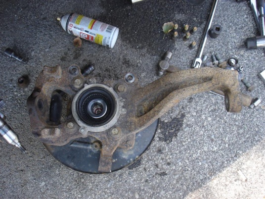
13) Now lift up the knuckle and remove the nut, and the knuckle will drop out. Be careful, it’s very heavy.
14) Remove snap ring and using a wire brush, clean around the top of the ball joint where it meets the lower control arm. Spray some penetrating oil around the top of the ball joint for ease of removal.
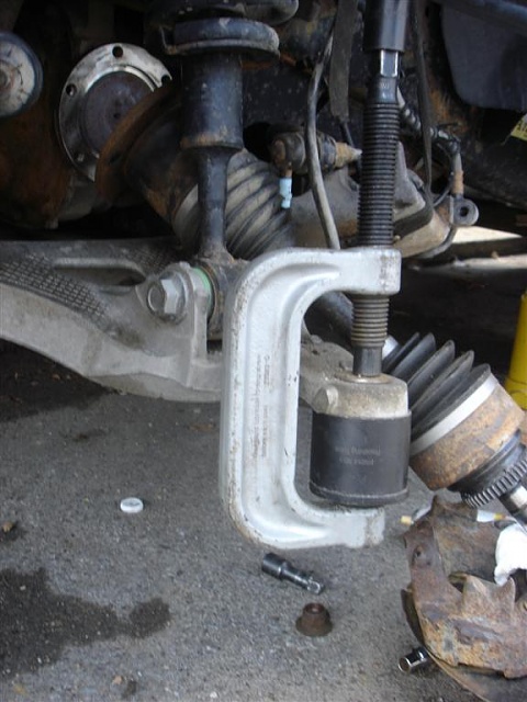
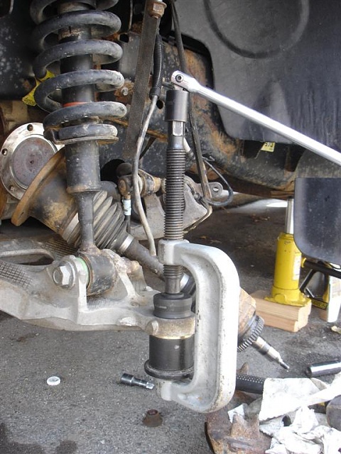
15) Connect the ball joint press as shown in the 3rd photo below and push the ball joint out of the lower control arm. You’ll have to really crank on the press until you hear it start to pop out. Try to line up the forcing screw of the press along the axis of the ball joint. Normally with cast iron assemblies on solid axles, a few whacks with the hammer can shock the housing, freeing the ball joint, but I wouldn’t recommend doing that on the aluminum lower control arm.
16) Install the new ball joint. I used the regular adapters to get it started and then finished the installation with the special Ford receiver cup, but a large socket would also work. My new Moog ball joints came with 90-degree grease fittings, which should face toward either the front or the rear in order to ease future greasing.
Reassembly:
1) Clean out the old grease with clean rags and lube the seals and hub a good quality all purpose grease. I used Mobil 1 red grease because it’s available almost anywhere. Avoid over greasing as this can cause the hub to overheat and/or grease to blow out the seals.
2) Clean and lube the outer CV joint splines, threads, and polished surfaces.
3) After reinstalling the knuckle to the lower ball joint stud (again, just a few turns on the nut to hold the knuckle in place), slip the outer cv joint into the hub assembly and install the 13 mm nut until axle starts to turn inside the hub. Be careful not to damage the polished surfaces of the cv joint or the inner hub seal as you do this. You can torque this to spec at the end.
4) Tighten the lower ball joint until it bottoms out.
5) Reinstall the halfshaft flange to the differential flange and sequentially torque the 12mm bolts in a star pattern up to 60 ft.-lbs. I used medium Loctite on these bolts.
6) Install the upper ball joint stud into the knuckle, and pull down on the control arm in order to engage the threads with the nut.
7) Install the tie rod and turn the nut until it bottoms out, but do not torque it down at this point. You’ll need an adjustable wrench and a 10 mm wrench or socket to prevent the stud from rotating while you do this. It’s actually easier to hold the nut and turn the stud itself.
8) Torque lower ball joint to 40 ft.-lbs.
9) Torque upper ball joint to 85 ft.-lbs. Use the same procedure as in step #7, but you’ll need a 9mm combination wrench or socket.
10) Torque lower ball joint to 95 – 111 ft.-lbs, keeping an to line up the eye of the stud with one of the slots on the nut. Install cotter pin. (Moog ball joints use 22mm nuts with cotter pins. OEM BJs use 24mm self-locking nuts.)
11) Torque tie rod self-locking nut to 85 ft.-lbs.
12) Install ABS Sensor & vacuum lines.
13) Install the brake rotor
14) Install caliper brackets and torque bolts to 148 ft.-lbs. Slide the pads onto the bracket, then install the caliper and torque the bolts to 22 ft.lbs.
15) Finally, torque the 13mm axle nut to 20 ft.-lbs. and tap the dust cap back on. Gently tap only around the outer edges with a plastic hammer to avoid damaging the cap.
16) Reinstall wheel and tighten lug nuts to 150 ft.-lbs. Start the car and pump the brake pedal until firm in order to seat the front brake pads, and take the car for a test drive.