In this article,i wan to share the guide on how to install blind spot information system (BLIS) for Ford F150 2015.Hope it helps!
Note: if using FORScan to program modules, prior to disassembly; save a backup copy of the current Driver’s Door Module & Passenger’s Door Module (DDM & PDM) As Built programming. This will simplify and expedite programming the replacement DDM & PDM.
How to Use FORScan to Backup Module Data File
FORScan Android/iOS/Window Free Download
Note: Prior to beginning, using FORScan or equivalent, check for any DTCs that may be present in any modules. Document the DTCs and clear. This step will assist in identifying any DTCs that were/were not created as a result of the following procedure.
Note: this BLIS installation guide assumes the vehicle has the XLT 302A level trim and already has fully functioning Non-King Ranch LED tail lamps (2015-17 HL3Z-13404-D RH/HL3Z-13405-DLH or 2018 JL3Z-13404-F RH/JL3Z-13405-F LH).
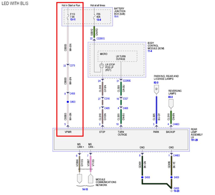
Installing LED tail lamps is most easily accomplished by replacing the 13A409 tail lamp harness with the JL3Z-13A409-G harness. JL3Z-13A409-G harness supports: BLIS, LED Tail/Reverse/Turn & Stop Lamps, LED Bed Lamps, Trailer Assist Lamp, Rear View Camera and Tail Gate Lock Actuator. Requires using FORScan to Disable Rear Lamp Outage: change BCM address 726-27-02 from xxxx xxxx x1xx (1 = Rear Lamp Outage Enabled) to xxxx xxxx x0xx (0 = Rear Lamp Outage Disabled).
Required Hardware:
(1) JL3Z-14D189-A Bracket – RH BLIS Module Mounting (Required w/2018 LED Tail Lamps)
or
(1) FL3Z-14D189-A Bracket – RH BLIS Module Mounting (Required w/2015 – 2017 LED Tail Lamps)
(1) JL3Z-14D189-B Bracket – LH BLIS Module Mounting (Required w/2018 LED Tail Lamps)
or
(1) FL3Z-14D189-B Bracket – LH BLIS Module Mounting (Required w/2015 – 2017 LED Tail Lamps)
(8) W715133-S900 Screw – BLIS Module Mounting Bracket to Tail Lamp Housing
(2) FL3Z-14C689-A Sensor – BLIS Module
(4) W505564-S450 Screw – BLIS Module to BLIS Module Mounting Bracket
(1) FL3Z-17682-AF Mirror RH (Trailer Tow w/black textured skull cap) or equivalent mirror with BLIS capability
(1) FL3Z-17683-AF Mirror LH (Trailer Tow w/black textured skull cap) or equivalent mirror with BLIS capability
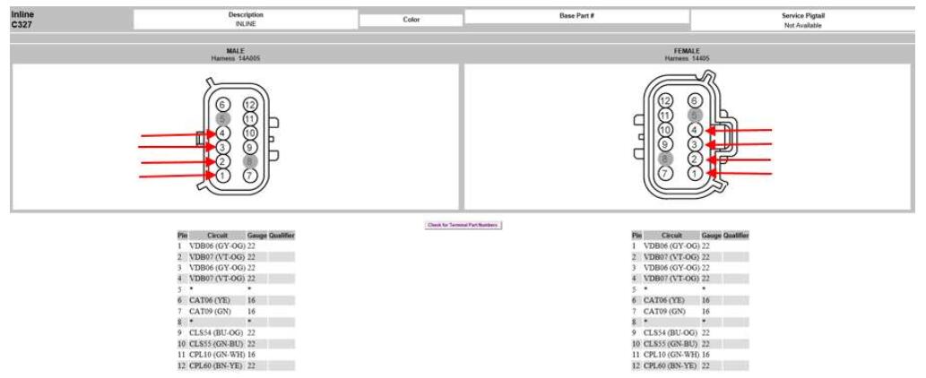
(4) EU2Z-14421-CA (Motorcraft part # WT-1013) Terminals – C405 Connector. Molex Part # 33000-0003
(4) DU2Z-14474-DA (Motorcraft part # WT-1003) Terminals – C327 Connector. Molex Part # 33012-2003
(1) DG9Z-14B291-WP LH Door Module – vehicles built on 10/20/14 thru 4/7/16
(1) DG9Z-14B291-WR RH Door Module – vehicles built on 10/20/14 thru 4/7/16
(1) FL3Z-14630-E RH Door Harness (Lariat wo/Tech. Pkg.) – required for vehicles with 8 pin mirror connecters
(1) FL3Z-14631-A LH Door Harness (Lariat wo/Tech. Pkg.) – required for vehicles with 8 pin mirror connecters
(20’) 9744 Belden (or equivalent) 4-Conductor (2 twisted pairs x 22 gauge) Wire
(20’) 83-8010 Grote (or equivalent) 3/8” polyethylene split wire loom
(8) 84-2150 Grote (or equivalent) 18-22 gauge (Red) butt splices w/heat shrink
(15) 6” black tie straps
Wiring Modifications:
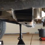
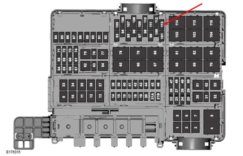
Confirm the presence of 7.5 amp fuse at location # F113 in the Power Distribution Box (Battery Junction Box – BJB).
This fuse provides 12V+ to the BLIS modules. This fuse should be present if vehicle is equipped with factory installed rear view camera.
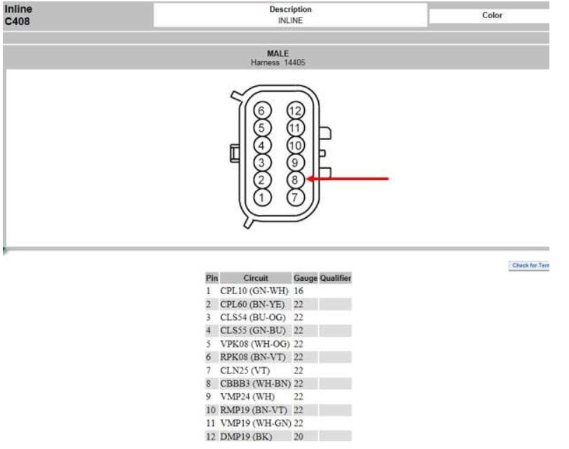
The C408 12 pin inline connector is located at the rear of the LH frame rail. Confirm the presence of WH-BN /CBBB3 wire at location # 8 of C408 male connector of the 14405 frame harness. This wire provides 12V+ to the BLIS modules. This wire should be present if vehicle is equipped with factory installed rear view camera.
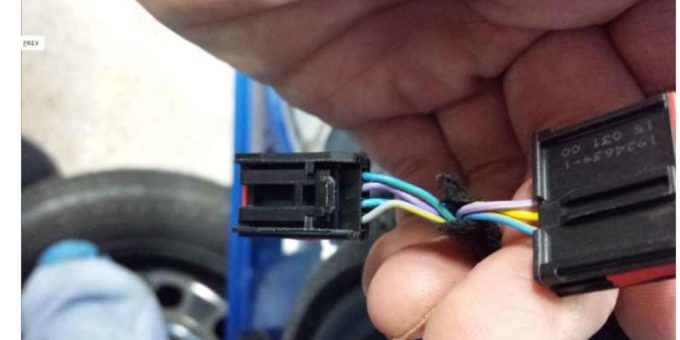
The C405 16 pin inline connector is located at the rear of the LH frame rail. Using (4) EU2Z-14421-CA (Motorcraft part # WT-1013) Terminals, the C405 male connector of the 14405 frame harness must have 4 wires added at location #s 4, 5, 12 & 13 for the CAN Bus circuit**.
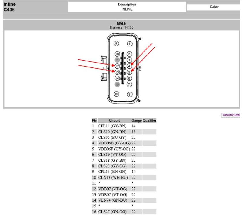
The 4 wires that were added to the C405 inline 16 pin male connector in the previous step must be routed from the rear of the vehicle along the LH frame rail and connected to the C327 female inline 12 pin connector of the 14405 frame harness using (4) DU2Z-14474-DA (Motorcraft part # WT-) Terminals at location #s 1, 2, 3 & 4 for the CAN Bus circuit**. The C327 12 pin inline connector is located in the engine compartment below the master cylinder on top of the LH fender well. These (4) additional wires will complete the CAN Bus circuit for the BLIS modules. Note: see attached BLIS wiring schematic below. Vehicles with halogen tail lamps wo/BLIS will have
(2) short jumper wires installed between terminals # 1 & 3 (GY-OG / VBBB06) and 2 & 4 (VT-OG / VBBB07) at the C327 female connector of the 14405 frame harness. These (2) jumper wires can be extracted from the 14405 frame harness and cut to allow connection of the (4) additional wires to the C327 female connector or (4) DU2Z- 14474-DA terminals can be used.
Note: The wiring at locations 1, 2, 3 & 4 (terminals 1 & 3 (GY-OG / VBBB06) and 2 & 4 (VT-OG / VBBB07) for the CAN Bus circuits should already be present at the C327 inline male connector of the 14A005 cab harness.
BLIS Wiring Schematic – CAN Bus Circuit
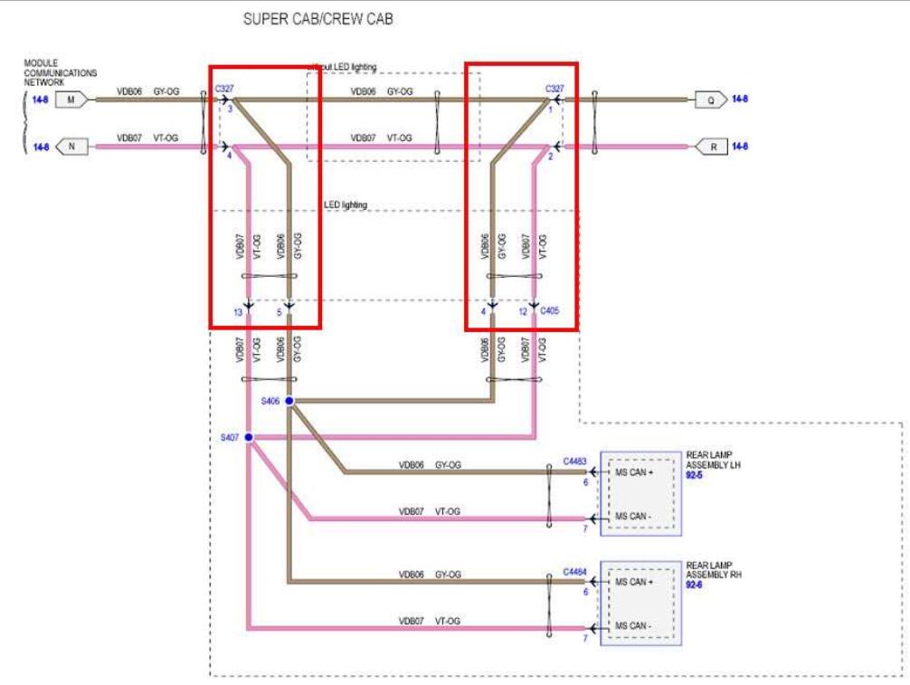
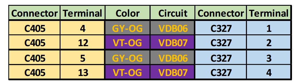
**Note: Circuits 4 & 12 to 1 & 2 and 5 & 13 to 3 & 4 should each be a separate twisted pair of 22 gauge wires.
Hardware Changes:
Install BLIS sensors & mounting brackets
Install mirrors with BLIS capability
Replace DDM & PDM
Replace both door harnesses: required if vehicle is currently equipped with 8 pin mirror connectors. Suggest using FL3Z-14630-E and FL3Z-14631-A Lariat wo/Technology Package door harnesses which support: power adjust, heat, turn signals, power fold & telescope, memory,auto dimming (driver’s side only), spot lamps, LED security approach lamps and BLIS:
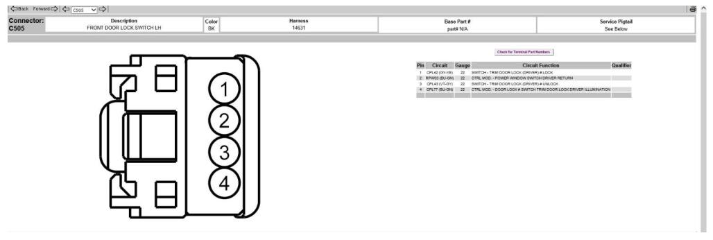
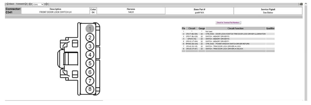
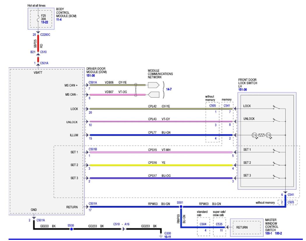
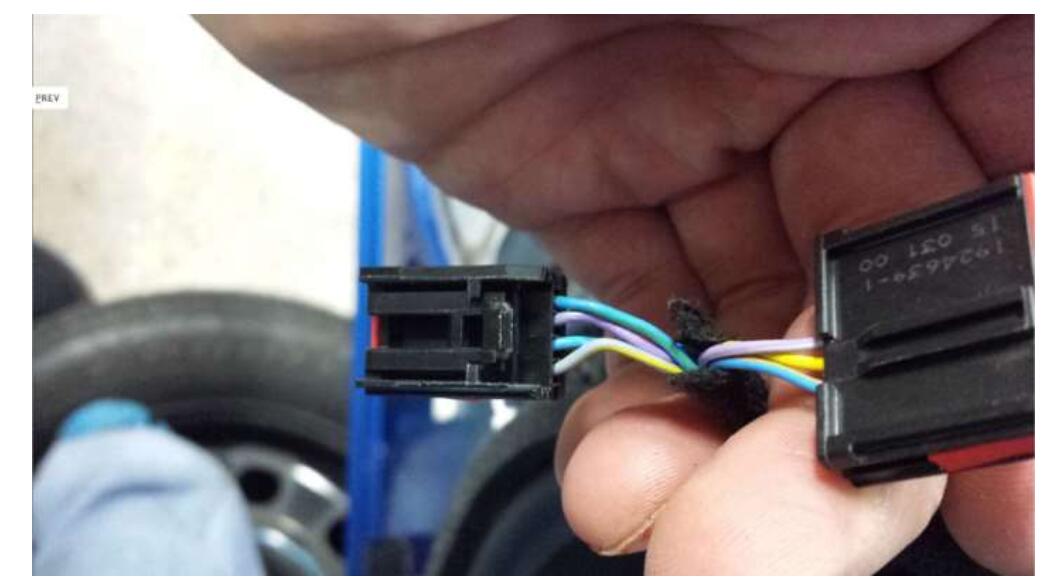
o XLT driver’s side door harness has a 4 pin C505 connector at the door lock switch. Lariat driver’s side door harness has 8 pin C541 connector at the door lock switch. 4 Wires from terminals #7, 6, 8 and 2 must be removed from C541 connector and transferred respectively to Pins 1, 2, 3 & 4 of C505 connector body. Refer to attached wiring diagrams. C541 8 pin door lock connector (with remaining 3 wires for memory circuit),exterior front door handle switch connectors (C543 & C634) and interior front door handle ambient lighting connectors (C573 & C649) won’t be used and should be neatly secured out of harm’s way.
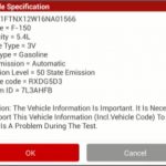
Module Programming Using FORScan:
IPC (Instrument Panel Cluster):
o 720-01-01 xxxx xxxx 7xxx (Enables Cross Traffic Alert Check Box in IPC)
o 720-03-01 6xxx xxxx (Enables Blind Spot Check Box in IPC)
DDM & PDM (Driver’s Door Module & Passenger’s Door Module):
o Program new DDM & PDM with original As Built values that were saved prior to disassembly.
o Make the following changes to DDM & PDM As Built values:
§ 740-04-01 x4xx xx (Driver’s Door Module) – Enables BLIS
§ 741-04-01 x4xx xx (Passenger’s Door Module) – Enables BLIS
SODL (Side Object Detection Left):
o 7C4-01-01 9800 0065
o 7C4-02-01 5D0A 0000 0035
o 7C4-02-02 0000 14E3
o 7C4-03-01 0B09 E3
o 7C4-04-01 5F0A 39
o 7C4-05-01 1E0A 0400 00FD
o 7C4-05-02 2541 38
o 7C4-06-01 1055 826E 80A7
o 7C4-07-01 4060 080A 199E
o 7C4-07-02 0FE3
o 7C4-08-01 3146 5445 573B – VIN # Specific
o 7C4-08-02 3106 – VIN # Specific
o 7C4-09-01 4546 3946 4B2A – VIN # Specific
o 7C4-09-02 441A – VIN # Specific
o 7C4-10-01 3133 3337 34DE – VIN # Specific
o 7C4-11-01 0046 0A23 0A5A – 2017 only
o 7C4-11-02 11EF – 2017 only
o 7C4-12-01 0603 E7- 2017 only
SODR (Side Object Detection Right):
o 7C6-01-01 9800 0067
o 7C6-02-01 5D0A 0000 0037
o 7C6-02-02 0000 14E5
o 7C6-03-01 0B09 E5
o 7C6-04-01 5F0A 3B
o 7C6-05-01 1E0A 0400 00FF
o 7C6-05-02 2541 3A
o 7C6-06-01 1055 826E 80A9
o 7C6-07-01 4060 080A 19A0
o 7C6-07-02 0FE5
o 7C6-08-01 3146 5445 573D – VIN # Specific
o 7C6-08-02 3108 – VIN # Specific
o 7C6-09-01 4546 3946 4B2C – VIN # Specific
o 7C6-09-02 441C – VIN # Specific
o 7C6-10-01 3133 3337 34E0 – VIN # Specific
o 7C6-11-01 0046 0A23 0A5C – 2017 only
o 7C6-11-02 11F1 – 2017 only
7C6-12-01 0603 E9 – 2017 only
Clear any DTCs that were created during programming of the modules and check for any DTCs that can’t be cleared.